Summary: Use a consistent case for PyTorch3D (matching the logo...): replace all occurrences of PyTorch3d with PyTorch3D across the codebase (including documentation and notebooks)

Reviewed By: wanyenlo, gkioxari

Differential Revision: D20427546

fbshipit-source-id: 8c7697f51434c51e99b7fe271935932c72a1d9b9
5.6 KiB
hide_title, sidebar_label
| hide_title | sidebar_label |
|---|---|
| true | Getting Started |
Renderer Getting Started
Architecture Overview
The renderer is designed to be modular, extensible and support batching and gradients for all inputs. The following figure describes all the components of the rendering pipeline.
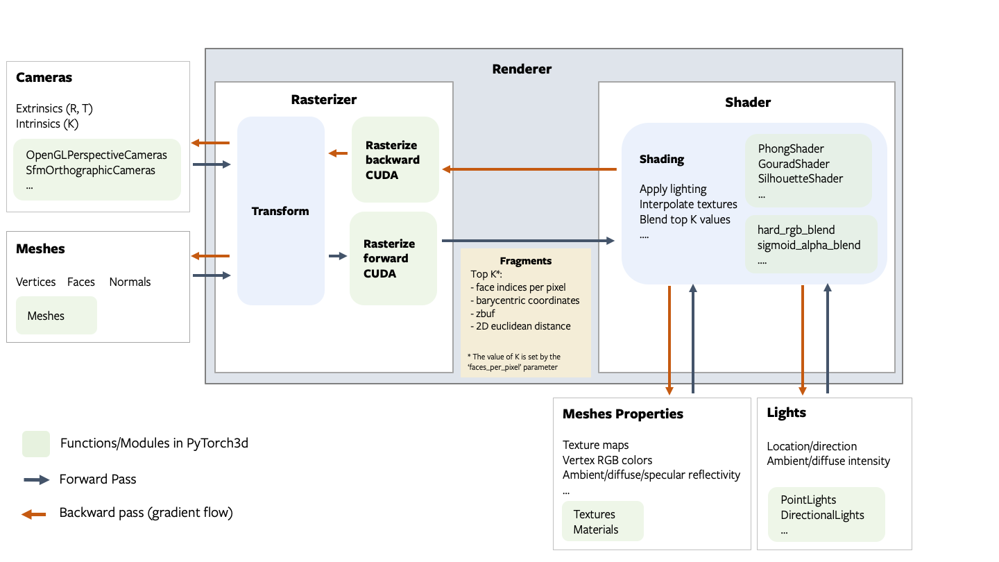
Fragments
The rasterizer returns 4 output tensors in a named tuple.
pix_to_face: LongTensor of shape(N, image_size, image_size, faces_per_pixel)specifying the indices of the faces (in the packed faces) which overlap each pixel in the image.zbuf: FloatTensor of shape(N, image_size, image_size, faces_per_pixel)giving the z-coordinates of the nearest faces at each pixel in world coordinates, sorted in ascending z-order.bary_coords: FloatTensor of shape(N, image_size, image_size, faces_per_pixel, 3)giving the barycentric coordinates in NDC units of the nearest faces at each pixel, sorted in ascending z-order.pix_dists: FloatTensor of shape(N, image_size, image_size, faces_per_pixel)giving the signed Euclidean distance (in NDC units) in the x/y plane of each point closest to the pixel.
See the renderer API reference for more details about each component in the pipeline.
NOTE:
The differentiable renderer API is experimental and subject to change!.
Coordinate transformation conventions
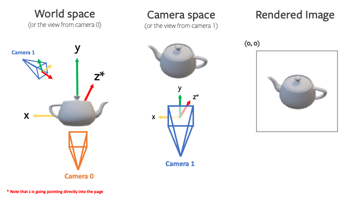
Rendering requires transformations between several different coordinate frames: world space, view/camera space, NDC space and screen space. At each step it is important to know where the camera is located, how the +X, +Y, +Z axes are aligned and the possible range of values. The following figure outlines the conventions used PyTorch3D.
For example, given a teapot mesh, the world coordinate frame, camera coordiante frame and image are show in the figure below. Note that the world and camera coordinate frames have the +z direction pointing in to the page.
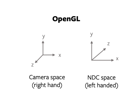
NOTE: PyTorch3D vs OpenGL
While we tried to emulate several aspects of OpenGL, there are differences in the coordinate frame conventions.
- The default world coordinate frame in PyTorch3D has +Z pointing in to the screen whereas in OpenGL, +Z is pointing out of the screen. Both are right handed.
- The NDC coordinate system in PyTorch3D is right-handed compared with a left-handed NDC coordinate system in OpenGL (the projection matrix switches the handedness).
A simple renderer
A renderer in PyTorch3D is composed of a rasterizer and a shader. Create a renderer in a few simple steps:
# Imports
from pytorch3d.renderer import (
    OpenGLPerspectiveCameras, look_at_view_transform,
    RasterizationSettings, BlendParams,
    MeshRenderer, MeshRasterizer, HardPhongShader
)

# Initialize an OpenGL perspective camera.
R, T = look_at_view_transform(2.7, 10, 20)
cameras = OpenGLPerspectiveCameras(device=device, R=R, T=T)

# Define the settings for rasterization and shading. Here we set the output image to be of size
# 512x512. As we are rendering images for visualization purposes only we will set faces_per_pixel=1
# and blur_radius=0.0. Refer to rasterize_meshes.py for explanations of these parameters.
raster_settings = RasterizationSettings(
    image_size=512,
    blur_radius=0.0,
    faces_per_pixel=1,
    bin_size=0
)

# Create a phong renderer by composing a rasterizer and a shader. Here we can use a predefined
# PhongShader, passing in the device on which to initialize the default parameters
renderer = MeshRenderer(
    rasterizer=MeshRasterizer(cameras=cameras, raster_settings=raster_settings),
    shader=HardPhongShader(device=device, cameras=cameras)
)
A custom shader
Shaders are the most flexible part of the PyTorch3D rendering API. We have created some examples of shaders in shaders.py but this is a non exhaustive set.
A shader can incorporate several steps:
- texturing (e.g interpolation of vertex RGB colors or interpolation of vertex UV coordinates followed by sampling from a texture map (interpolation uses barycentric coordinates output from rasterization))
- lighting/shading (e.g. ambient, diffuse, specular lighting, Phong, Gouraud, Flat)
- blending (e.g. hard blending using only the closest face for each pixel, or soft blending using a weighted sum of the top K faces per pixel)
We have examples of several combinations of these functions based on the texturing/shading/blending support we have currently. These are summarised in this table below. Many other combinations are possible and we plan to expand the options available for texturing, shading and blending.
| Example Shaders | Vertex Textures | Texture Map | Flat Shading | Gouraud Shading | Phong Shading | Hard blending | Soft Blending |
|---|---|---|---|---|---|---|---|
| HardPhongShader | ✔️ | ✔️ | ✔️ | ||||
| SoftPhongShader | ✔️ | ✔️ | ✔️ | ||||
| HardGouraudShader | ✔️ | ✔️ | ✔️ | ||||
| SoftGouraudShader | ✔️ | ✔️ | ✔️ | ||||
| TexturedSoftPhongShader | ✔️ | ✔️ | ✔️ | ||||
| HardFlatShader | ✔️ | ✔️ | ✔️ | ||||
| SoftSilhouetteShader | ✔️ |